#1.3 Bistable 555 Timer

Disclaimer: I’m following the amazing series of videos from Ben Eater using his electronic built kit for the 8 bits computer. This series of post is only there for my personnal understanding about electronic and this amazing project. I ablsolutly recommand you to watch his series of videos instead of reading this post of course ! Play-List-Link
Disclaimer 2: I’m not an expert at all, Just a beginner who wants to learn, I stay tuned for corrections or advice! Thanks !
Switch
So far, so good, we have now 2 working mods for the clock module.
- The first one is an Astable Clock, which means the clock pulse is stable in time and we can change the speed with a potentiometer.
- The second mod is a Monostable Clock, which means that the clock pulse is always in one stable state, the “unpressd” state.
The final mod using a 555 time is a Bistable Clock, we are going to switch between Astable and Monostable using a Switch.
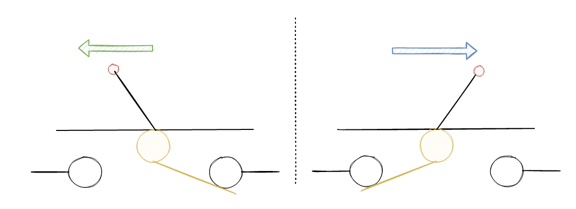
Bouncing Problem
Here is a simple example of what we could use to switch the output between the two mods
Debouncing - 555 Timer
Like before we can use the 555 timer for the bouncing problem, more precisely we are going to use SR Latch as a debouncing device.
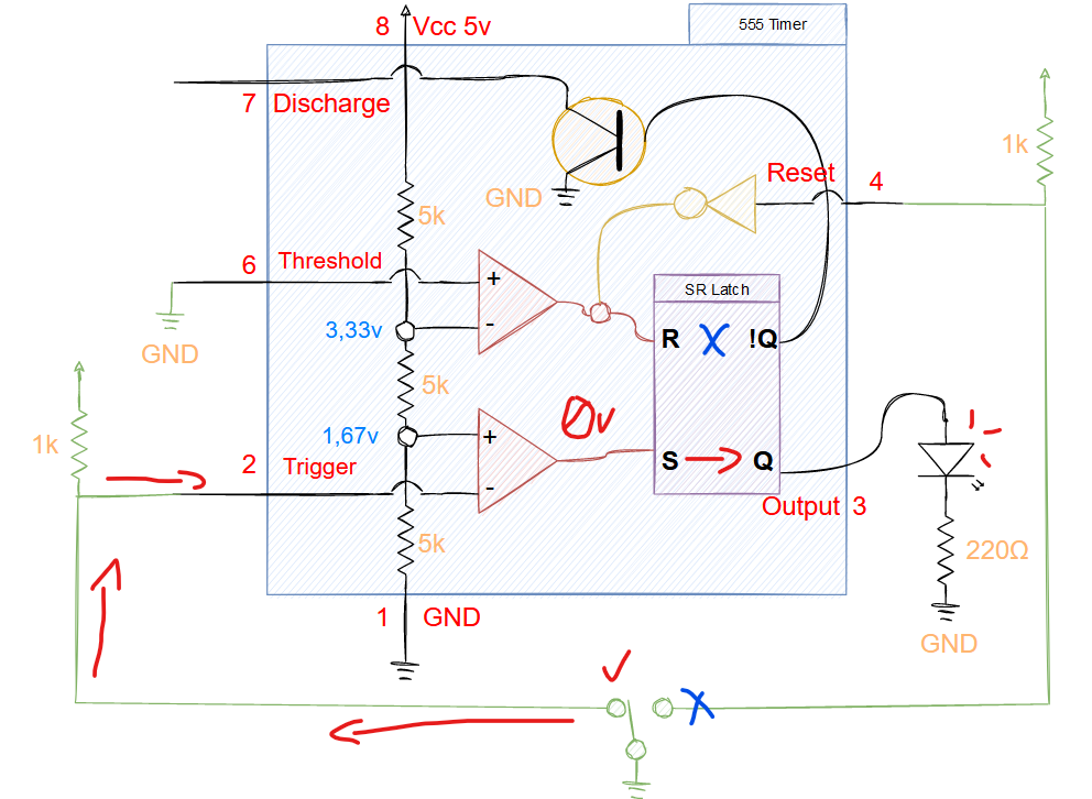
S Pin ON
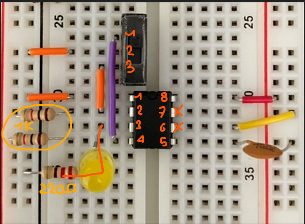
So, as we can see we don’t need PIN 6 and 7. Instead, we are going to use PIN 4 which is used to RESET SR Latch.
When the S is ON, the Switch will input 0v into the S so the LED will be ON.
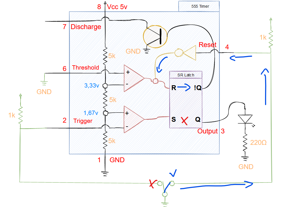
R Pin ON
On the other hand, the RESET pin is used when the switch is OFF on it (GND) will trigger the R PIN on SR Latch and the LED will be OFF
Final Switch
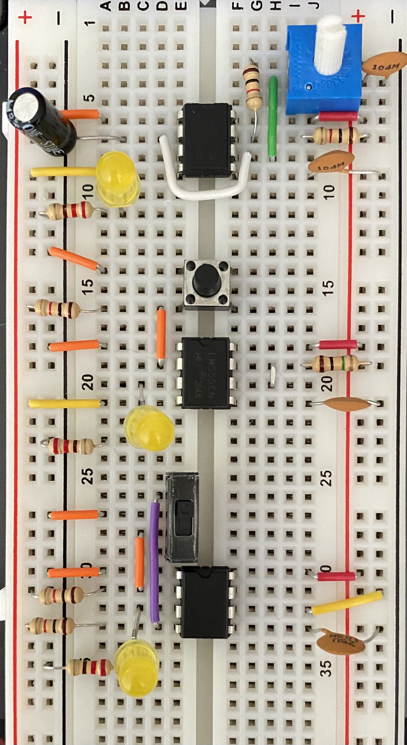
Here is the final part of the Bistable mod of this clock.
Next Part
In the next part, we are going to set up the Logic part of this switch so it will be related to the output of both previous mod.